Ok...let's have a look at this again. First up, if you're using Doepfer exclusively, the case size needs to be kicked up considerably. Their modules don't require chopstick-fingers and have clear layouts and great circuitry, but they tend toward the large side. So, before we get going here, we're gonna punch this up to 126 hp courtesy of THIS: https://www.ericasynths.lv/shop/enclosures/studio/1x126hp-skiff-case/ It's got way more space without being huge, the power is ample, and it supports up to 57mm depths...which is important with Doepfer, as a number of their modules exceed the typical 40-ish millimeter depth. Oh, and that's a kickass price (EUR 310) for something this sizable.
100% Doepfer. And this time, I blew the timing section WAY up. What've we got here...?
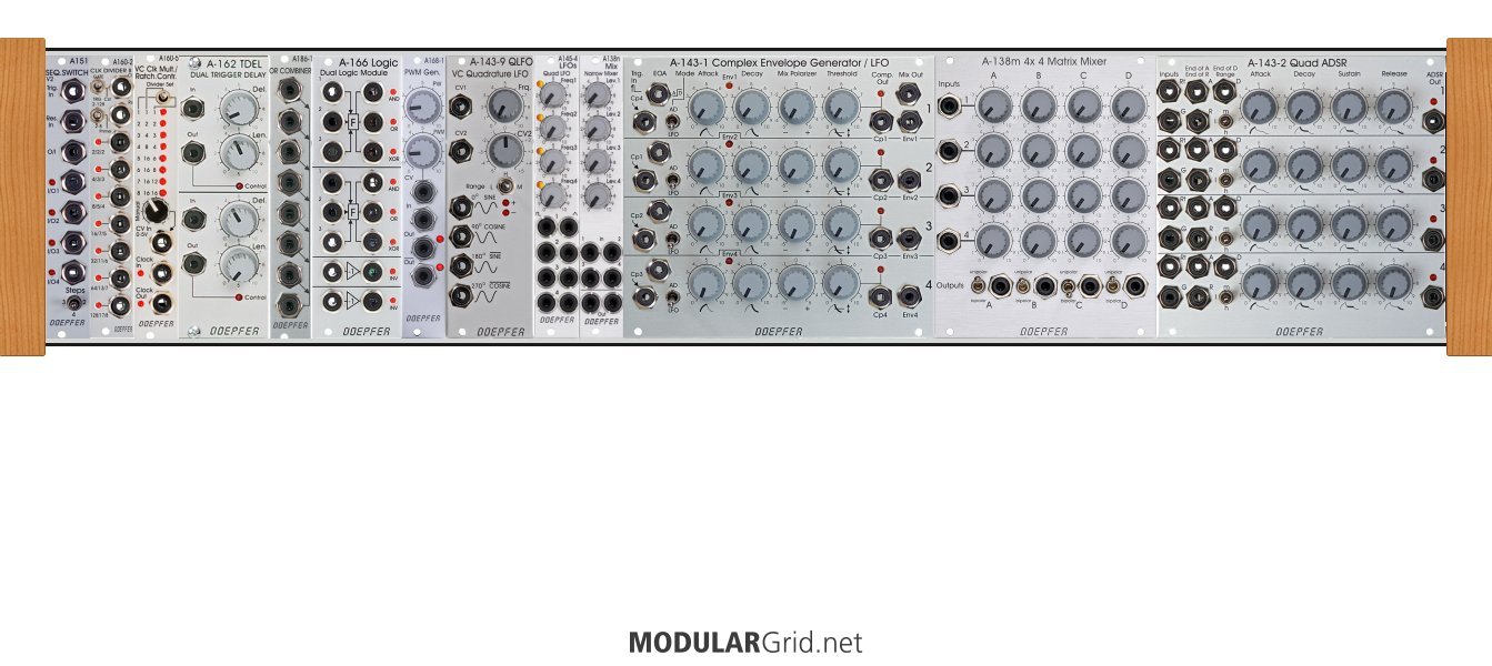
First is your timing. The first module is a bidirectional switch that switch between two to four in/outs to a single in/out. Then the clock divider and the clock multiplier for ratcheting. Right after that are the trigger delays, then there's a gate/trigger "integrator" and a Boolean logic module, then a "PWM" module that can actually be used to square off other waveforms for LFO-dependant gates. This can also work as a waveshaper for external VCOs. Now, what's going on here is this...Boolean logic takes incoming gate signals and subjects them to conditional states that either output a gate or nothing. OR outputs a gate when any gate is present at the logic stage, but not when there's none or both. AND will output a gate when ONLY there's both gates present. And of course, the inverse versions are also present via the two inverters. This allows you to wholesale manipulate the timing pulses in ways that can't happen without a Boolean logic module and its "pals".
After that, five LFOs. The quadrature LFO is CVable, then there's four non-CV LFOs followed by a 4-in mixer to create composite LFO curves. As for the why behind the quadrature LFO, that module allows you to have four identical LFO sines, save that each one is 90 degrees rotated from the previous output. This is useful for a pile of things...automated crossfading, weird panning strategies, and with the "PWM" module you can take that and generate CV-dependant gate pulses. You can also mix quadrature curves to generate some very strange results.
Then for the "meat", I went with the large quad AD and ADSR modules because these also contain "end of..." patchpoints which can ALSO fire things off via their triggers. The Quad AD also has comparators on each stage to send a gate when the envelopes are either above or below the set voltage threshold. And between these two big modules, I dropped in a Matrix Mixer...basically, it's a "performance controller" for mixing/altering/attenuating any of the voltage curve signals, with four inputs and four outputs, allowing each output to have a different mixture of the incoming modulation signals.
The only thing I really didn't have the space for here would be the noise/random module(s). If this went to a 6U 84 or 104 hp cab, though, there would be ample room for those and a few more bits of troublemaking. But this starts to show the possibilities that open up when you expand the cab from the small 3U x 84 skiff. And it WILL fit the big AD and ADSR quads as far as depth is concerned.