

ModularGrid uses so-called cookies to ensure it's so-called functionality. We also use dubious tracking scripts. Find out more in the Privacy Policy. We use cookies and wanna let you know.
Got it.
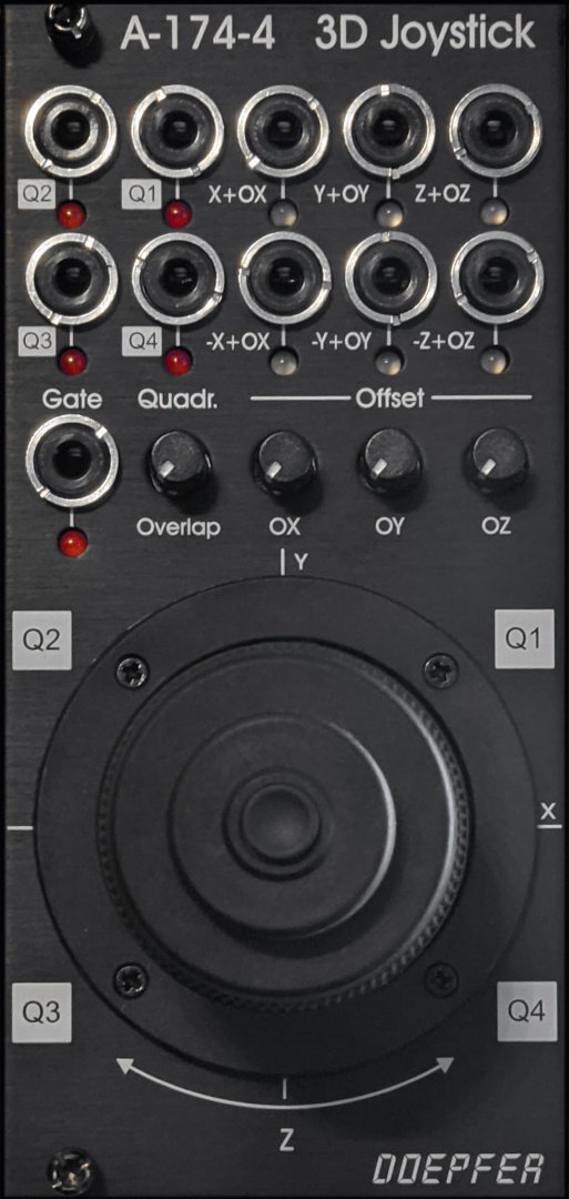
A-174-4 Joy Stick II Black Edition
http://www.doepfer.de/a1744.htm
If you had an Unicorn Account you could see a chart with the price development of this module and the average price asked for this module.
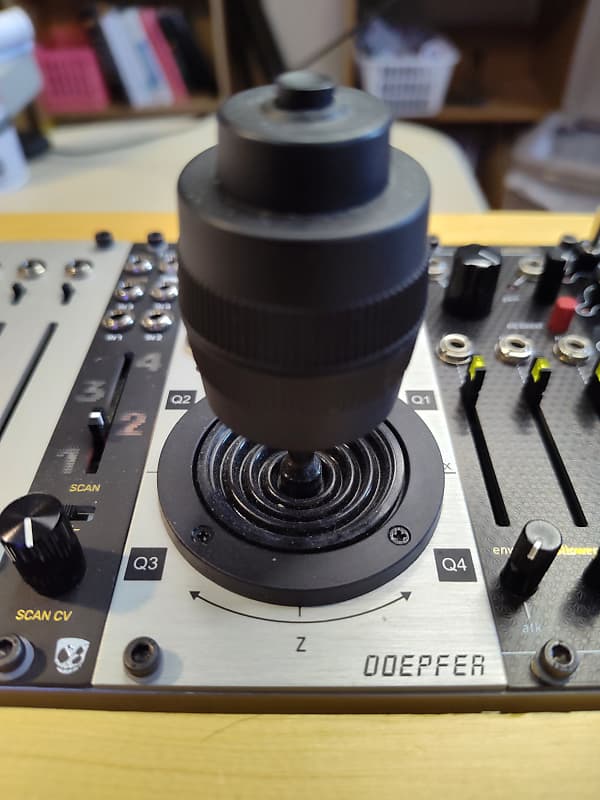
Barely used 3D joystick. Plenty of life left in this bad boy. Kept in a smoke-free home studio.From the maker:Module A-174-4 modules outputs three control voltages generated by a spring-loaded X/Y cross potentiometer (so-called joy stick) and a Gate signal. The control voltages for X and Y are controlled by the X and Y position of the joystick in the usual way. The third control voltage Z is controlled by the rotation of the spring-loaded joystick knob. The Gate signal is generated by a button at the center/top of the joystick knob.For each control voltage the non-inverted signal (X, Y, Z) as well as the inverted signal with adjustable offset (-X+XO, -Y+YO, -Z+ZO) are available. The generic joystick control voltages are bipolar, i.e. they range from typ. -5V (lowest position) via 0V (center position) to typ. +5V (highest position). The "Overlap" switches can be used to add a fixed offset voltage of typ. +5V to the non-inverting output in question so that the output voltage range changes to typ. 0...+10V (rather than -5...+5V). That's necessary if e.g. a VCA has to be controlled, which requires a pure positive control voltage range. The switches are named "overlap" because they allow the overlapping of the non-inverting CV output (X, Y, Z) with the inverting output (-X+XO, -Y+YO, -Z+ZO) for crossfading applications. With the overlap switch "on" and appropriate setting of the offset control it's possible to obtain a control voltage range of 0...+10V for the non-inverting output and +10V...0V (i.e. same range but opposite direction) for the inverting output.The offset voltages which are added to the inverting outputs can be adjusted by means of three small potentiometers. That way different kinds of control voltage ranges are possible, e.g.-5V ... +5V for the non-inverting output and +5V ... -5V for the inverting output ( Overlap = off, Offset = 0)0 ... +10V for the non-inverting output and +10V ... 0V for the inverting output ( Overlap = on, Offset = max)-5V ... +5V for the non-inverting output and +10V ... 0V for the inverting output ( Overlap = off, Offset = max)0 ... +10V for the non-inverting output and +5V ... -5V for the inverting output ( Overlap = on, Offset = 0)On top of this the four quadrant voltages Q1, Q2, Q3 and Q4 are available. A quadrant voltage becomes positive when the joystick is positioned in the quadrant in question.Each CV output is equipped with an LED that displays the present voltage.
This offer was fetched from reverb.com. You cannot contact the seller via ModularGrid. You have to visit their site.
Look up onDisclaimer: Modules listed for sale on the ModularGrid Marketplace are offered explicitly by their respective owners. ModularGrid is not affiliated to the sellers and takes no legal responsibility in any transaction.
The internet is a rough place and fraudulent behavior can occur. If you are concerned about dealing with strangers consider buying your module at an authorized dealer.