

ModularGrid uses so-called cookies to ensure it's so-called functionality. We also use dubious tracking scripts. Find out more in the Privacy Policy. We use cookies and wanna let you know.
Got it.
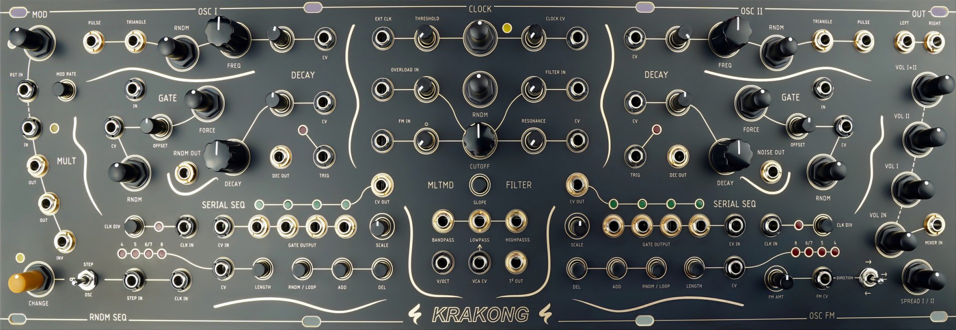
Duophonic Generative Synthesizer
https://www.st-modular.de/krakong
If you had an Unicorn Account you could see a chart with the price development of this module and the average price asked for this module.
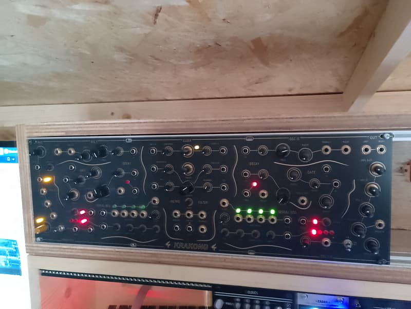
Up for sale is this monster of a module, a sonic playground, I built this from a kit, all working 100%.there is a small mark on the faceplate on second photo under the LED that says 4 above it, not sure how I done that :(, please check KRAKONG is a duophonic generative synthesizer with a sequencer per voice, FM crossover modulation, an additional random modulation sequencer, one multimode filter with VCA, a buffered multiple and a resettable LFO. The design includes a collection of manual controls and connections for patching and CV control. It fits into a standard Eurorack case with at least 80 HP (3U).Each of the unit's two voices consists of a triangle and a square wave oscillator, a shift register sequencer, a decay envelope generator and a filter-based gate. In addition to the two synthesizer voices, which can be manually distributed in the stereo field, a third ring-modulated output of the two voices can be mixed to the main output. The tempo of all sequencers is determined by a clock generator, which can be controlled internally or synchronised externally to any voltage (audio and CV).This musical instrument has a complete structure that allows for a wide range of sonic possibilities, from rhythmic drum patterns and tamed sonic chaos to textural and rough synth-sounds. The essence of this unit lies in the exploration of the interplay between the elements of the synthesiser, using the three sequencers and filters, manual controls and modulation patch points. It can be powered by a standard Eurorack PSU or a small ST Modular PSU PCB that can be built separately.INPUTS, OUTPUTS & FEATURES2 Oscillators1 Ring-modulated Output of the two Oscillators1 CV OSC FM Cross-Modulation 2 CV Filter-based Gates2 CV Decay Envelope Generators1 CV Multi-mode Filter with two External Inputs and VCA1 Noise Output2 Shift Register Sequencers1 Random Modulation Sequencer1 CV Clock Generator1 Resettable LFO1 Buffered Multiple with Inverted Output1 Mixer with stereo distribution (panning)OSC I and OSC IIPULSE – Output of the PULSE waveformTRIANGLE – Output of the TRIANGLE waveformRNDM – Amount of random modulation of the RNDM SEQ applied to the oscillator´s frequency.FREQ – Manual control of the oscillators´s frequency.FREQ CV Input – CV frequency input with attenuator. The oscillators don´t track exactly 1V/Oct. The MOD´s square wave output is normalized to the OSC I CV input. The MOD´s triangle wave output is normalized to the OSC II CV input. NOISE OUT – Output of the internal NOISE GENERATORGATE (OSC I & OSC II)IN – Audio input. The oscillator´s TRIANGLE output is normalized to this input.RNDM - Amount of random modulation of the RNDM SEQ applied to filter. This knob also acts as a attenuator for the GATE CV input.CV – CV input for the GATE cutoff. The RNDM SEQ CV output is normalized to this input.OFFSET – GATE cutoff offsetFORCE – Amount of DECAY CV applied to the GATEResonance of the OSC gates can be adjusted via a trimmer on the PCBDECAY (OSC I & OSC II)TRIG – CV input for triggering the DECAY envelope. The SERIAL SEQ TRIG output is normalized to this input.DEC OUT – DECAY output (OSC I Decay output can be set to inverted via jumper on the PCB)CV – CV DECAY input with attenuator. The RNDM SEQ CV output is normalized to this input.DECAY – Manual control of the DECAY lengthSERIAL SEQ (OSC I & OSC II)CLK IN – Sequencer clock input. The CLOCK GENERATOR´s output is normalized to this input.CLK DIV – The normalized CLOCK GENERATOR input can be divided by 2 or 8 (selectable via jumper on PCB).CV IN – Changes the locked note per clock according to an incoming CV signal. This signal is mixed with an internal noise source that generally generates random notes for the sequencer.GATE OUTPUT – Random or looped GATESCV OUT – Random or looped PITCH CV generated from a noise and CV input source.SCALE – Range of the pitch of CV OUTLENGTH – Select the length of a SEQUENCE. You can choose 4, 5, 6 or 7 (selectable via jumper on the PCB) or 8 steps. Please note that a change of the sequence length might also change the notes that are locked per clock signal, even in LOOP mode.LENGTH CV – CV control for selecting the sequence lengthRNDM/LOOP – Button to LOOP a sequence. If it is not looped it will generate random notes and gates.ADD – When pressed simultaneously with a CLOCK signal, it adds a random note and gate to the sequence.DEL – When pressed simultaneously with a CLOCK signal, it deletes a note and gate from the sequence.MOD (Resettable LFO)MOD KNOB – Manual control of the LFO RATEMOD RATE – Changes the RANGE of the LFO RATE from fast to slow.RST IN – Resets the LFO cycle on an incoming trigger signal.MULT (1 to 3 Buffered Multiple)IN – Multiple input. The MOD triangle waveform is normalized to this input.OUT (2x) – Buffered output of the multiplied signal.INV – Buffered and inverted output of the multiplied signal .RNDM SEQ (Random Modulation Sequencer)CHANGE – Turn this knob to create new random sequences or loop themSTEP/∞/OSC SWITCH – Controls if the CHANGE button is influenced either via the STEP IN input or the OSC I PULSE waveform. In mid-position no additional changes are applied to the CHANGE button.STEP IN – CV input to control the CHANGE knob (if SWITCH is set to STEP) in order to created steps of looped and random sequences.CLK IN – CLOCK input for the RNDM SEQ. The CLOCK GENERATOR´s output is normalized to this input.RNDM OUT – Output of the RANDOM MODULATION SEQUENCERCLOCK (Internal Clock Generator)CLOCK – Manual control of the CLOCK rateCLOCK CV – CV input with attenuator to control the clock rate. The RNDM SEQ CV output is normalized to this input.EXT CLK – External Clock input that overrides the internal clock. Any signal can be patched to this input (CV or audio).THRESHOLD – Sets a voltage threshold at which a clock pulse is generated. With a low threshold, clock pulses are already generated for very low voltages and conversely with a high threshold, clock pulses are only generated at peak voltages. In this way, you can use an audio drum loop, for example, to generate a clock signal and control the amount of clocks generated.MLTMD FILTER (Multi-Mode Filter)CUTOFF – Manual control of the filter´s CUTOFF frequencyRNDM - Amount of random modulation of the RNDM SEQ applied to filter. OVERLOAD IN – External input with attenuator. If you turn the attenuator past 12 o'clock, the incoming signal is starting to clip softly.FILTER IN - External input with attenuator.FM IN – Frequency Modulation input with attenuverter (bipolar). The internal LFO Triangle waveform is normalized to this input.RESONANCE – Feedback of the filter output to the input. This goes as far as self-oscillation.RESONANCE CV – CV input for RESONANCE controlSLOPE – This button changes the LOWPASS and BANDPASS FILTER SLOPE from 2-pole (12db) to 4-pole (24db).BANDPASS/LOWPASS/HIGHPASS – Filter output of the corresponding filter modesV/OCT – CV input with 1V/OCT tracking. This way you can play the filter with self-oscillating resonance as a third synthesizer voice.VCA CV - Voltage controlled amplifier input that only affects the LOWPASS output.T² – Pre-Filter ring-modulated output of OSC I and OSC II triangle waveformsOSC FM (Oscillator FM Cross-Modulation)FM AMT – Amount of frequency modulation applied to the target (OSC I, OSC II or both)FM CV – CV input to control the frequency modulation amountDIRECTION – Choose the direction of frequency modulation: OSC I modulating OSC II, OSC II modulating OSC I or both modulation each other.OUT (Mixer and OSC I & OSC II Panning)LEFT/RIGHT – Stereo OutputVOL I+II – Volume control of the T² output before it is routed to the MULTIMODE FILTER. If you want to use the MLTMD FILTER only with another sound source, simply turn this volume down.VOL II – Volume control of OSC IIVOL I – Volume control of OSC IMIXER IN – External mixer input. Audio is directly routed to OUT.VOL IN – External mixer input volume controlSPREAD – Extends the panning for OSC I and OSC II in opposite directions and thus distributes the two outputs in the stereo field. The ring-modulated output of
This offer was fetched from reverb.com. You cannot contact the seller via ModularGrid. You have to visit their site.
Look up onDisclaimer: Modules listed for sale on the ModularGrid Marketplace are offered explicitly by their respective owners. ModularGrid is not affiliated to the sellers and takes no legal responsibility in any transaction.
The internet is a rough place and fraudulent behavior can occur. If you are concerned about dealing with strangers consider buying your module at an authorized dealer.