Accord R.U.L.E
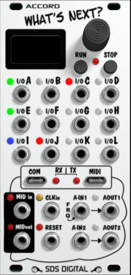
- Dimensions
- 12 HP
- 34 mm deep
- Current Draw
- 80 mA +12V
- 60 mA -12V
- 0 mA 5V
- Price
This Module is a prototype or in a concept phase.
MG ID: 55637
Advanced Math Module
12 configurable Input / Output jacks with RGB LED's, Color LCD, Panel & USB-c MIDI I/O, Clock & Reset, dual VC
What is it??
The R.U.L.E (formerly "What's Next") is a universal CV/Gate/Trigger I/O module that obeys Rules / Algorithms that you enter into memory to offer ultimate control around your rack. No matter how big or small a function is assigned the response is predictable and accurate.
Without the RULE, patching even simple logic / CV gates and event sequences can become both tedious and complex very quickly. A simple fuction like switching VCO's according to pitch, would require a lot of utility modules to achieve seamlessly. Doing this with the RULE is simple. To make things even more interesting, there's also Sequencers, LFO's, delays, Random/probabilty generators, quantizers, Envelope generators, and even a frequency counter built in that can be triggered and activated whenever you want, played at any speed, and provide an accurate reproduction of previous sessions every time thanks to flash memory.
Because the 12 jack grid can be input or output, the RULE is very flexible in what it can do. i.e. One input could trigger 11 outputs, or many inputs hitting a certain voltage or state as defined could cause a trigger output, voltage, or even a MIDI output or sequence to occur. When you consider that these I/O can run at audio rates, a whole new world of intelligent signal control opens up. Output retention / collision is also monitored so is safe to use with anything over modular voltage range.
For example, if your algorithm is set to simply add the CV input at Jack A with the input at Jack B, with the result at jack C, the inputs and outputs are automatically configured and a 1.00 volt input on A and B with result in 2.00 volts at jack C. Or, perhaps you only want this voltage to update when Jack D has a high on it. A conditional statement in front of the A+B statement will only allow updates to Jack C when Jack D is set to high.
No remembering syntax or referring to the manual to program it. The statements are composed from drop-down lists to make programming as simple as point and click via the encoder. Lets say you have 2 voltages (A & B) and you want to trigger an envelope whenever A is above B with an attack rate reflecting the amount A is above B. Here's a Rule listing example to do that:
OUTC = CV.A x CV.B....Jack C will have the product of the CV's on A & B
VAR2 = CV.A - CV.B.....Variable 2 hold the result of Jack A - Jack B
IF VAR2 > 0..................If variable 2 >0 (Jack A > Jack B) continue
OUTD = HI...................Jack D becomes a logic output that gets set high
VAR3 = VAR2÷10........ Variable 3 holds 1/10th of Variable 2
ENV2 = ATK + VAR3...Add Variable 3's value to the Attack setting in Envelope 2
ELSE........If the conditioanl above was false, the following will execute instead
OUTD = LO......As Jack A's CV is no longer above Jack B's, Jack D falls back low
ENDIF ...... To close the conditional "IF" statement
Because of the present political turmoil, I am no longer fast tracking this module, rather, taking my time developing it. If you have been following development you may have noticed the display change to a larger crisper version. It is still color and a larger LCD so no worries about burn-in or squinting to see entries etc.
For updates and more information on the RULE, follow the website link. Modified July 2026
See video for basic methodology and information:
Marketplace sell and buy used modules
Right Now on eBay