divide by n
- Dimensions
- 6 HP
- 25 mm deep
- Current Draw
- 5 mA +12V
- 2 mA -12V
- 0 mA 5V
- Price
- $130
Available as an assembled Module and as a DIY project.
This Module is currently available.
MG ID: 57104
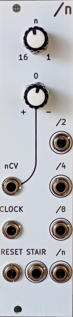
voltage controlled clock/frequency divider
Any +ve going signal applied to CLOCK advances a 4-bit binary counter feeding a 'staircase' voltage generator.
A comparator compares the staircase to the voltage sum of the 'n' knob and nCV input to reset the counter, giving a variable pattern length of 1 to 16 clock pulses.
/n is the main output, giving one output pulse for every n clock pulses.
/2, /4, /8 give one pulse every 2, 4, and 8 clock pulses but are reset when /n goes high so the actual division/pattern you get is dependent on the current value of n.
As n gets lower some or all of the divider outputs will be identical.
When n=4 the /4, /8, and /n outputs will all be /4, for example.
When n=2 all outputs will be /2.
When n=1 all outputs will follow the clock input.
All 4 pulse outputs have the same width as the incoming clock signal, and are only high while the clock input is high.
STAIR is a falling 'staircase' waveform derived from the internal counter/staircase mixed with the control voltage. As n decreases the amplitude decreases and frequency increases.
When n=16 you get a stepped sawtooth approx ±5V with a period of 16 clock cycles.
When n=2 the output is less than 1V square-ish* wave half the clock frequency.
When n=1 STAIR outputs nothing.
The STAIR output has a somewhat noticeable 30-40 microsecond glitch/artifact at the final step before resetting, please see pictures on webshop. It didn't greatly bother me so I left it there for 'character'.
A +ve signal on RESET sets all four counter bits back to 1 at any time, just remember that the divider outputs will only go high while the signal on CLOCK is also high.
Marketplace sell and buy used modules
| Date | Region | Description | Price | Seller |
|---|---|---|---|---|
| EU | WHITE or BLACK panel - freshly built, with love paypal... | €115,00 | RTFM | |
| EU | The overall condition of this freshly built module is p... | €115,00 | KitKatAndy |
2 Users are observing this
 Serge Modular Divide by N Comparator
 Random Source Serge Divide by N
 Nonlinearcircuits 1/n [Divide by N]
 Random Source Serge Divide by N
 Random Source Random Source Serge
Right Now on eBay

USA

These merchants probably sell this module. Huh?