- Dimensions
- 1 U
Micro Module
- Current Draw
- 15 mA 5V
- Price
- $47
This Module is currently available.
MG ID: 57320
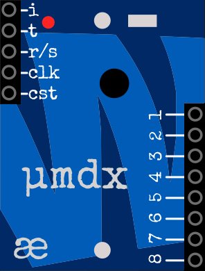
micro MIDI demultiplexer
µmdx performs channel-demultiplexing from a single IMDI input to 8 channel outputs – like a slimmed-down mb/1 without the TRS input (for that you'll need the mi/mo).
Originally the modules was desiged to be used in conjunction with the mi/mo to perform MIDI channel extraction in the micro-module format, however it can also be used with modules which generate data on multiple channels (such as CVMx) to further break out channel-related data streams.
Output Assignment mode
| Output pin | Mode A channel outputs | Mode B channel outputs | Mode C channel outputs |
|---|---|---|---|
| 1 | 1 | 9 | 1 & 2 |
| 2 | 2 | 10 | 3 & 4 |
| 3 | 3 | 11 | 5 & 6 |
| 4 | 4 | 12 | 7 & 8 |
| 5 | 5 | 13 | 9 & 10 |
| 6 | 6 | 14 | 11 & 12 |
| 7 | 7 | 15 | 13 & 14 |
| 8 | 8 | 16 | 15 & 16 |
Controls
- button — cycles between output assignment modes (see table above)
Connectivity
All inputs & outputs are IMDI streams.
Inputs
- i - the IMDI input - connect this to the channel output of an IMDI generator as listed above.
Outputs
- left side:
- t : IMDI Thru - a buffered copy of the input data, to be connected to the IMDI input of a subsequent module.
- r/s 'Run/Stop' signal:
- Outputs 5v when a clock-start message has been received;
- Outputs 0v when a clock-stop message is received.
- clk a clock signal derived from the 24ppqn MIDI clock signal. It is possible to divide this down to other rates (e.g. 1/16th pulses) by using the online editor which can be found here
- cst outputs a 5ms pulse when a MIDI clock start message is received, this is typically used to reset sequencer modules so that they always start in the same location. No pulse is generated when a MIDI-continue is received;
- right side:
- 1-8 IMDI channel outputs, allocated as above.
submitted Feb 26th, 15:09 by wonkystuff
Marketplace sell and buy used modules
Right Now on eBay

This page contains affiliate links from eBay, Reverb.com and other partners for which ModularGrid may be compensated.